Reactive energy management
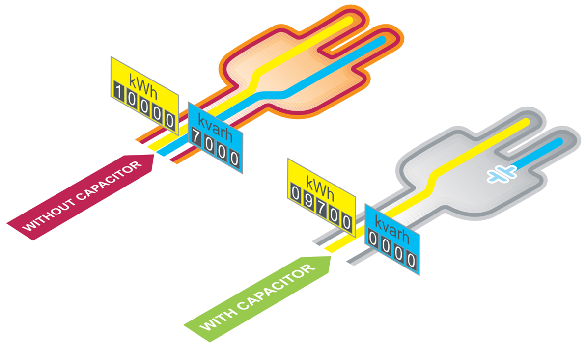
In electrical networks, reactive energy results in increased line currents for a given active energy transmitted to loads. The main consequences are:
- Need for oversizing of transmission and distribution networks by utilities,
- Increased voltage drops and sags along the distribution lines,
- Additional power losses.
This results in increased electricity bills for industrial customers because of:
- Penalties applied by most utilities on reactive energy,
- Increased overall kVA demand,
- Increased energy consumption within the installations.
Reactive energy management aims to optimize your electrical installation by reducing energy consumption, and to improve power availability. Total CO emissions are also reduced. Utility power bills are typically reduced by 5% to 10%*.


Improve electrical networks and reduce energy costs
This is typically achieved by producing reactive energy close to the consuming loads, through
connection of capacitor banks to the network.
Benefits of reactive energy management
Optimized reactive energy management brings economic and technical advantages as follows:
- Savings on the electricity bill
- Eliminating penalties on reactive energy and decreasing kVA demand.
- Reducing power losses generated in the transformers and conductors of the installation.
Example:
Loss reduction in a 630 kVA transformer PW = 6,500 W with an initial Power Factor = 0.7.
With power factor correction, we obtain a final Power Factor = 0.98. The losses become: 3,316 W, i.e. a reduction of 49%.
Increasing available power
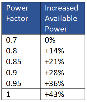
A high-power factor optimizes an electrical installation by allowing better use of the components. The power available at the secondary of a MV/LV transformer can therefore be increased by fitting power factor correction equipment on the low voltage side.
The table opposite shows the increased available power at the transformer output through improvement of the Power Factor from 0.7 to 1.

Reducing installation size
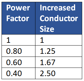
Installing power factor correction equipment allows conductor cross-section to be reduced, since less current is absorbed by the compensated installation for the same active power.
The opposite table shows the multiplying factor for the conductor cross-section with different power factor values.

Reducing voltage drops in the installation
Installing capacitors allows voltage drops to be reduced upstream of the point where the power factor correction device is connected. This prevents overloading of the network and reduces harmonics, so that you will not have to overrate your installation.
If you require further information on our Power Factor Correction. Get in touch HERE!


